
Plasma Welding

Process characteristics
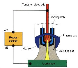
Plasma welding is very similar to TIG as the arc is formed between a pointed tungsten electrode and the workpiece. However, by positioning the electrode within the body of the torch, the plasma arc can be separated from the shielding gas envelope. Plasma is then forced through a fine-bore copper nozzle which constricts the arc. Three operating modes can be produced by varying bore diameter and plasma gas flow rate:- Microplasma: 0.1 to 15A.
The microplasma arc can be operated at very low welding currents. The columnar arc is stable even when arc length is varied up to 20mm. - Medium current: 15 to 200A.
At higher currents, from 15 to 200A, the process characteristics of the plasma arc are similar to the TIG arc, but because the plasma is constricted, the arc is stiffer. Although the plasma gas flow rate can be increased to improve weld pool penetration, there is a risk of air and shielding gas entrainment through excessive turbulence in the gas shield. - Keyhole plasma: over 100A.
By increasing welding current and plasma gas flow, a very powerful plasma beam is created which can achieve full penetration in a material, as in laser or electron beam welding. During welding, the hole progressively cuts through the metal with the molten weld pool flowing behind to form the weld bead under surface tension forces. This process can be used to weld thicker material (up to 10mm of stainless steel) in a single pass.
Power source
The plasma arc is normally operated with a DC, drooping characteristic power source. Because its unique operating features are derived from the special torch arrangement and separate plasma and shielding gas flows, a plasma control console can be added on to a conventional TIG power source. Purpose-built plasma systems are also available. The plasma arc is not readily stabilised with sine wave AC. Arc reignition is difficult when there is a long electrode to workpiece distance and the plasma is constricted, Moreover, excessive heating of the electrode during the positive half-cycle causes balling of the tip which can disturb arc stability.Special-purpose switched DC power sources are available. By imbalancing the waveform to reduce the duration of electrode positive polarity, the electrode is kept sufficiently cool to maintain a pointed tip and achieve arc stability.
Arc starting
Although the arc is initiated using HF, it is first formed between the electrode and plasma nozzle. This 'pilot' arc is held within the body of the torch until required for welding then it is transferred to the workpiece. The pilot arc system ensures reliable arc starting and, as the pilot arc is maintained between welds, it obviates the need for HF which may cause electrical interference.Electrode
The electrode used for the plasma process is tungsten-2%thoria and the plasma nozzle is copper. The electrode tip diameter is not as critical as for TIG and should be maintained at around 30-60 degrees. The plasma nozzle bore diameter is critical and too small a bore diameter for the current level and plasma gas flow rate will lead to excessive nozzle erosion or even melting. It is prudent to use the largest bore diameter for the operating current level.Note: too large a bore diameter, may give problems with arc stability and maintaining a keyhole.
Plasma and shielding gases
The normal combination of gases is argon for the plasma gas, with argon plus 2 to 5% hydrogen for the shielding gas. Helium can be used for plasma gas but because it is hotter this reduces the current rating of the nozzle. Helium's lower mass can also make the keyhole mode more difficult.Applications
Microplasma welding
Microplasma was traditionally used for welding thin sheets (down to 0.1 mm thickness), and wire and mesh sections. The needle-like stiff arc minimises arc wander and distortion. Although the equivalent TIG arc is more diffuse, the newer transistorised (TIG) power sources can produce a very stable arc at low current levels.Medium current welding
When used in the melt mode this is an alternative to conventional TIG. The advantages are deeper penetration (from higher plasma gas flow), and greater tolerance to surface contamination including coatings (the electrode is within the body of the torch). The major disadvantage lies in the bulkiness of the torch, making manual welding more difficult. In mechanised welding, greater attention must be paid to maintenance of the torch to ensure consistent performance.Keyhole welding
This has several advantages which can be exploited: deep penetration and high welding speeds. Compared with the TIG arc, it can penetrate plate thicknesses up to l0mm, but when welding using a single pass technique, it is more usual to limit the thickness to 6mm. The normal methods is to use the keyhole mode with filler to ensure smooth weld bead profile (with no undercut). For thicknesses up to 15mm, a vee joint preparation is used with a 6mm root face. A two-pass technique is employed and here, the first pass is autogenous with the second pass being made in melt mode with filler wire addition.As the welding parameters, plasma gas flow rate and filler wire addition (into the keyhole) must be carefully balanced to maintain the keyhole and weld pool stability, this technique is only suitable for mechanised welding. Although it can be used for positional welding, usually with current pulsing, it is normally applied in high speed welding of thicker sheet material (over 3 mm) in the flat position. When pipe welding, the slope-out of current and plasma gas flow must be carefully controlled to close the keyhole without leaving a hole.
Back to the Job Knowledge index.
Disclaimer and Copyright © TWI 25th May 1996
Search | Site map | Help | Contact us | Links | Home