|
1. Process fundamentals
The plasma arc cutting process is illustrated in Fig.a. The basic principle is that the arc formed between the
electrode and the workpiece is constricted by a fine bore, copper nozzle. This increases the temperature and
velocity of the plasma emanating from the nozzle. The temperature of the plasma is in excess of 20 000ˇĆC and
the velocity can approach the speed of sound. When used for cutting, the plasma gas flow is increased so that
the deeply penetrating plasma jet cuts through the material and molten material is removed in the efflux
plasma.
The process differs from the oxy-fuel process in that the plasma process operates by using the arc to melt the
metal whereas in the oxy-fuel process, the oxygen oxidises the metal and the heat from the exothermic reaction
melts the metal. Thus, unlike the oxy-fuel process, the plasma process can be applied to cutting metals which
form refractory oxides such as stainless steel, aluminium, cast iron and non-ferrous alloys.
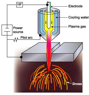
Fig.a dual gas
2. Power source
The power source required for the plasma arc process must have a drooping characteristic and a high voltage.
Although the operating voltage to sustain the plasma is typically 50 to 60V, the open circuit voltage needed to
initiate the arc can be up to 400V DC.
On initiation, the pilot arc is formed within the body of the torch between the electrode and the nozzle. For
cutting, the arc must be transferred to the workpiece in the so-called 'transferred' arc mode. The electrode
has a negative polarity and the workpiece a positive polarity so that the majority of the arc
energy (approximately two thirds) is used for cutting.
3. Gas composition
In the conventional system using a tungsten electrode, the plasma is inert, formed using either argon,
argon-H2 or nitrogen. However, as described in Process variants, oxidising gases, such as air or oxygen,
can be used but the electrode must be copper with hafnium.
The plasma gas flow is critical and must be set according to the current level and the nozzle bore diameter.
If the gas flow is too low for the current level, or the current level too high for the nozzle bore diameter,
the arc will break down forming two arcs in series, electrode to nozzle and nozzle to workpiece.
The effect of 'double arcing' is usually catastrophic with the nozzle melting.
4. Cut quality
The quality of the plasma cut edge is similar to that achieved with the oxy-fuel process. However, as the plasma
process cuts by melting, a characteristic feature is the greater degree of melting towards the top of the metal
resulting in top edge rounding, poor edge squareness or a bevel on the cut edge. As these limitations are
associated with the degree of constriction of the arc, several torch designs are available to improve arc
constriction to produce more uniform heating at the top and bottom of the cut.
5. Process variants
The process variants, Figs. a to e, have principally been designed to improve cut quality and arc stability,
reduce the noise and fume or to increase cutting speed.
-
Dual gas
The process operates basically in the same manner as the conventional system but a secondary gas shield is
introduced around the nozzle, Fig. 2a. The beneficial effects of the secondary gas are increased arc constriction
and more effective 'blowing away' of the dross. The plasma forming gas is normally argon, argon-H2 or nitrogen
and the secondary gas is selected according to the metal being cut.
The advantages compared with conventional plasma are:
- Reduced risk of 'double arcing'
- Higher cutting speeds
- Reduction in top edge rounding
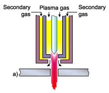
Fig.b water injection
Water injection
Nitrogen is normally used as the plasma gas. Water is injected radially into the plasma arc, Fig. b, to induce
a greater degree of constriction. The temperature is also considerably increased, to as high as 30,000ˇĆC.
The advantages compared with conventional plasma are:
- Improvement in cut quality and squareness of cut
- Increased cutting speeds
- Less risk of 'double arcing'
- Reduction in nozzle erosion
Water shroud
The plasma can be operated either with a water shroud, Fig. c, or even with the workpiece submerged some 50 to
75mm below the surface of the water. Compared with conventional plasma, the water acts as a barrier to provide
the following advantages:
- Fume reduction
- Reduction in noise levels
Improved nozzle life
In a typical example of noise levels at high current levels of 115dB for conventional plasma, a water shroud was
effective in reducing the noise level to about 96dB and cutting under water down to 52 to 85dB.
As the water shroud does not increase the degree of constriction, squareness of the cut edge and the cutting
speed are not noticeably improved.
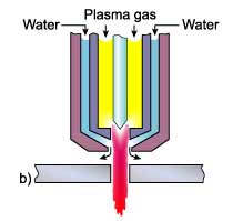
Fig.c water shroulded
Air plasma
The inert or unreactive plasma forming gas (argon or nitrogen) can be replaced with air but this requires a
special electrode of hafnium or zirconium mounted in a copper holder, Fig. 2d. The air can also replace water
for cooling the torch. The advantage of an air plasma torch is that it uses air instead of expensive gases.
It should be noted that although the electrode and nozzle are the only consumables, hafnium tipped electrodes
can be expensive compared with tungsten electrodes.
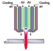
Fig.d air plasma
High tolerance plasma
In an attempt to improve cut quality and to compete with the superior cut quality of laser systems,
High Tolerance Plasma Arc cutting (HTPAC) systems are available which operate with a highly constricted plasma.
Focusing of the plasma is effected by forcing the oxygen generated plasma to swirl as it enters the plasma
orifice and a secondary flow of gas is injected downstream of the plasma nozzle, Fig. 2e. Some systems have
a separate magnetic field surrounding the arc. This stabilises the plasma jet by maintaining the rotation
induced by the swirling gas.
The advantages of HTPAC systems are:
- Cut quality lies between a conventional plasma arc cut and laser beam cut
- Narrow kerf width
- Less distortion due to smaller heat affected zone
HTPAC is a mechanised technique requiring precision, high-speed equipment. The main disadvantages are that
the maximum thickness is limited to about 6mm and the cutting speed is generally lower than conventional
plasma processes and approximately 60 to 80% the speed of laser cutting.
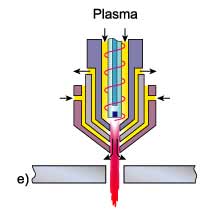
Fig.e high tolerance
|