-
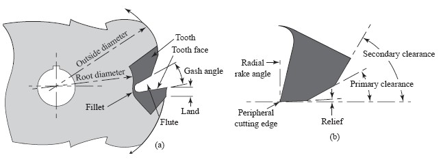
OUTSIDE DIAMETER. The outside diameter is the diameter of the cylinder passing through the peripheral cutting
edges.
ROOT DIAMETER. The root diameter is the diameter of the circle passing tangent to the bottom of the fillet.
-
SIDE TOOTH LENGTH. Length of the raised land along the side tooth. Required to calculate the number of
resharpenings available and the modification possibilities.
CUTTER FACE WIDTH. The cutter face is the surface at the side or end of the cutter body which is perpendicular
to the axis of the cutter. The distances between the two faces of plain, helical and side milling cutters, or the
length of the outside diameter cylinder is the cutter width, if small, or cutter length,with respect to the diameter.
TOOTH FACE. The tooth face is that surface of the cutting tooth against which the chip is forced in the metal
cutting operation.
LAND. The land is that part of the back of the tooth adjacent to the cutting edge which is relieved to avoid
interference between itself and the surface being machined. A raised land permits numerous resharpenings before a
secondary clearance has to be ground.
CUTTING EDGE. The cutting edge is the intersection of the face of the tooth with the leading edge of the land.
FLUTE. The flutt, is the chip space between the back of one tooth and the face of the following tooth.
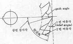
RELIEF ANGLE. The peripheral relief angle is the angle between the surface formed by the land and a tangent
to the cutter outside circle passing through the cutting edge in a diametral plane. It is to prevent the land from
rubbing on the surface of the work being cut. Relief and clearance are measured in degrees or in radial fall in
inches at a certain specified distance back of the cutting edge on the land. For this latter measurement, a dial
indicator may be used to measure the radial fall in thousandths of an inch from the outside or cutting edge diameter
back of the cutting edge.
RADIAL RAKE ANGLE. The radial rake angle of a milling cutter is the angle formed in a diametral plane between
the face of the tooth and a radial line passing through the cutting edge. This may be positive, negative, or
zero degree.
AXIAL RAKE ANGLE OR HELICAL RAKE. When a milling cutter has helical teeth, that is, when its cutting edge is
formed along a helix about the cutter axis, the resulting rake is called helicall rake. If the cutting edge is
straight, its rake is axial rake. The axial rake or helical rake angle is the angle formed between the line of
the peripheral cutting edge and the axis of the cutter, when looking radially at the point of intersection.
This applies in the case of helical mills, half-side mills, staggered tooth mills, face mills, and metal slitting
saws having face cutting edges.
GASH DEPTH. Gash depth is the distance from the outside diameter of the cutter to the fillet radius or root
diameter.
- FILLET RADIUS. The fillet radius is the curved surface at the bottom of the flute which joins the face of one
tooth to the back of the tooth immediately ahead.
DISH OR CONCAVITY. The progressive decrease in cutter width from the periphery toward the center.
RADIAL OFFSET. The radial offset of a milling cutter is the physical dimension that a tooth is
behind(for positive rake) or ahead (for negative rake) of a center line drawn parallel with flat, tooth face.
It is calculated by multiplying the sine function of the radial rake angle times the radius of the milling cutter.
DEPTH OF RECESS. The distance from the cutting edge on the land of the side tooth (or the hub which is the
same width as the cutter) to the recess is the depth of recess. This dimension is required to determine width and
angle modification limits.
HUB DIAMETER. The hub is the raised ground section between the bore and recess. It is the same width as the
cutter. Collar spacers butt adjacent to the hub for holding and spacing of the cutter on the arbor. The hub diameter
dimension is required to determine the allowable depth or cut and clearance between cutter and workpiece.