|
Backgear (본서에 없기 때문에 보충함)
As its name implies, "backgear" is a gear mounted at the back of the headstock (although in practice
it is often located in other positions) that allows the chuck to rotate slowly with greatly-increased
turning power. For a novice the ability to run a workpiece slowly might seem unnecessary, but a large-diameter
casting, fastened to the faceplate and run at 200 r.p.m. (around the bottom speed commonly found on a
lathe without backgear) would have a linear speed at its outer edge beyond the turning capacity of
a small lathe. By engaging backgear, and so reducing r.p.m. but increasing torque, even the largest
faceplate-mounted jobs can be turned successfully.
Screwcutting also requires slow speeds, typically between 25 and 50 r.p.m. - especially if the operator
is a beginner, or the job tricky. A bottom speed in excess of those figures (as found on most Far Eastern
and some European "Continental" machines) means that screwcutting - especially internally, into blind
holes - is, in effect, impossible. These lathes are advertised as "screwcutting" but what that really
means is just power sliding - a power feed along the bed. With these machines even if you go to the trouble
of making up a complex pulley system to reduce the spindle speed (like the early Atlas 9-inch) you will
find the torque required when turning large diameters at slow speeds causes the belts to slip. The only
solution is a gear-driven low speed - and so a properly-engineered small lathe, with a backgear fitted,
not only becomes capable of cutting threads but can also tackle heavy-duty drilling, big-hole boring and
large-diameter turning and facing; in other words, it is possible to use it to the very limits of its
capacity and strength. To show how important backgear has always been considered examine the small
English-made metal turning lathes made from the mid 19th century onwards: nearly every one was so
equipped.
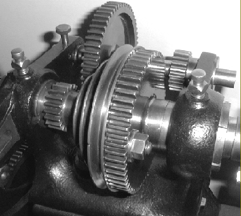
backgear
|
backgear
|
The backgear is a clever but essentially simple mechanism probably conceived by Richard Roberts, an English
engineer and prolific inventor, around 1817.
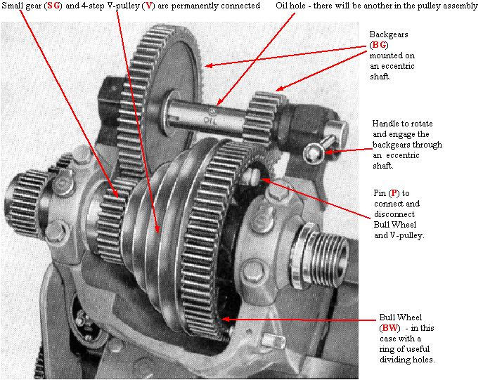
In the picture above (a 1934 Atlas lathe) the 4-step V-pulley (V) has a small gear (SG) permanently attached
to its smaller end. The entire length of V-pulley and gear are bushed - and able to rotate freely on the
headstock spindle.
The large "Bull Wheel" (BW) is keyed to the spindle (and always rotates with it) and can be connected to
the V-pulley - and disconnected from it - by a pin (P) which is often spring-loaded.
In normal use the V-pulley is rotated by the drive belt and the spindle made to turn through the action
of the pin driving the Bull Wheel.
To use the backgear the lathe is stopped, pin is withdrawn (leaving the V-pulley and small gear free
to rotate) and the Backgear (BG) rotated on its eccentric shaft to bring it into mesh with the other gears.
On starting the lathe the action is now as follows: the pulley is rotated by the drive belt, the small gear
(SG) on the V-pulley (V) drives the larger of the two backgears - which in turn causes the small gear at
the other end of its shaft to rotate. This smaller gear drives the Bull Wheel (B) , and hence the
spindle, at a greatly reduced speed (normally in the order of 6 : 1) but increased torque.
Examination of the headstock pulley and the backgear shaft may well reveal the presence of oil holes;
these are important for, when working in backgear, considerable forces are being transmitted and the
whole assembly requires frequent lubrication if it is to work reliably. If the pulley is allowed to
seize on the headstock spindle considerable time - and possibly money - will have to be spent in order
to free it off.
Not all backgears engage like the one above some, like the one on the 1906 Drummond illustrated below,
slide into position whilst others are held in a forked bracket and slide into position. Some are even
built into the larger end of the headstock pulley and operate on a "epicyclic" principal, not unlike
that of a Sturmey-Archer hub gear on a bicycle.
There is often a small mark on the pulley to show where the pin through the bull wheel will engage
(if this is missing, one could, with advantage, be made). The face of the pulley is often not a simple
flat surface but hollowed out with a small drilled boss provided to carry the pin; if just pushed in at
random and the lathe started the pin will catch on the side of the boss and bend.
If backgear constantly jumps out of engagement there may be an adjustable friction screw, hidden away at the back of the casting, that will solve the problem.
On this wonderfully-original, early Drummond lathe the Bull Wheel and Drive Pulley are connected together
not with a pin, but a substantial nut and bolt. The "head" of the bolt engages with a slot in the periphery
of the pulley wheel (not the notch cut in the pulley to show the operator where this is).
The backgear is slid sideways into its operating position - and held by a pin that passes through the
casting
and engages with a slot cut in the backgear shaft.
|
