|
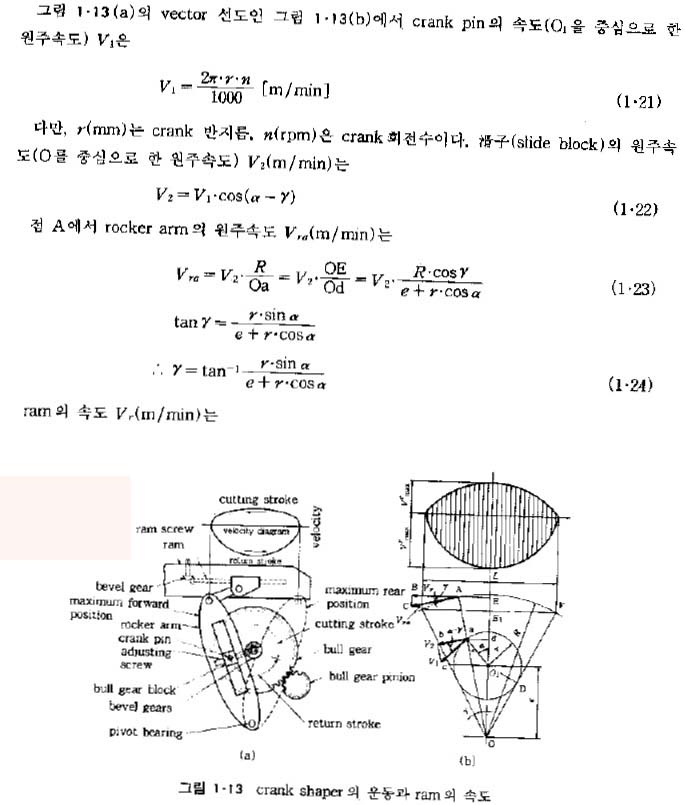
The cutting speed of the tool across the work will vary during the stroke as shown by the velocity diagram.
The maximum is at the center of the stroke. However, if the cutting speed chosen is somewhat on the slow side,
the average speed may be used, and computations are greatly simplified.
Although the ratio varies somewhat,several shapers have a linkage using 220 degrees of the cycle for the cutting
stroke and 140 degrees for the return stroke. This is close to a 3:2 ratio.
In setting up a mechanically operated shaper, the length of cut(in inches) is known, and the cutting
speed(in feet per minute) is selected according to the kind of metal being cut. It is then necessary to compute
the strokes per minute since that is how the shaper speed is controlled. Such calculations are beyond the scope
of this text.
The stroke per minute available on a shaper will vary according to the size of the shaper. The larger shapers will
have lower speeds. A 16´´ shaper may have speeds of 27 to 150 strokes per minute, while a 24´´ shaper will have
10 to 90 strokes per minute speeds available.
|


 절삭가공학 p. 8 ~ 9, 서남섭 저, 동명사 발행