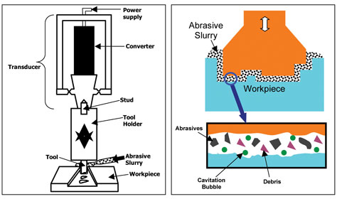
High-frequency, low-amplitude energy is transmitted to the tool assembly. A constant stream of abrasive slurry passes
between the tool and workpiece. The vibrating tool, combined with the abrasive slurry, uniformly abrades the material,
leaving a precise reverse image of the tool shape. The tool does not come in contact with the material; only the abrasive
grains contact the workpiece.
In the UM process, a low-frequency electrical signal is applied to a transducer, which converts the electrical energy
into high-frequency (~20 KHz) mechanical vibration. This mechanical energy is transmitted to a horn and
tool assembly and results in a unidirectional vibration of the tool at the ultrasonic frequency with a known amplitude.
The standard amplitude of vibration is typically less than 0.002 in. The power level for this process is in the range of
50 to 3000 watts. Pressure is applied to the tool in the form of static load.
A constant stream of abrasive slurry passes between the tool and the workpiece. Commonly used abrasives include diamond,
boron carbide, silicon carbide and alumina, and the abrasive grains are suspended in water or a suitable chemical solution.
In addition to providing abrasive grain to the cutting zone, the slurry is used to flush away debris. The vibrating tool,
combined with the abrasive slurry, abrades the material uniformly, leaving a precise reverse image of the tool shape.
Ultrasonic machining is a loose abrasive machining process that requires a very low force applied to the abrasive grain,
which leads to reduced material requirements and minimal to no damage to the surface. Material removal during the UM
process can be classified into three mechanisms: mechanical abrasion by the direct hammering of the abrasive particles
into the workpiece (major), micro-chipping through the impact of the free-moving abrasives (minor), and cavitation-induced
erosion and chemical effect (minor).2
Material removal rates and the surface roughness generated on the machined surface depend on the material properties and
process parameters, including the type and size of abrasive grain employed and the amplitude of vibration, as well as
material porosity, hardness and toughness. In general, the material removal rate will be lower for materials with high
material hardness (H) and fracture toughness (KIC).
UM effectively machines precise features in hard, brittle materials such as glass, engineered ceramics, CVD SiC, quartz,
single crystal materials, PCD, ferrite, graphite, glassy carbon, composites and piezoceramics. A nearly limitless number
of feature shapes?including round, square and odd-shaped thru-holes and cavities of varying depths, as well as OD-ID
features?can be machined with high quality and consistency (see Figure 3). Features ranging in size from 0.008 in. up
to several inches are possible in small workpieces, wafers, larger substrates and material blanks. Aspect ratios as
high as 25-to-1 are possible, depending on the material type and feature size.
Unlike conventional machining methods, ultrasonic machining produces little or no sub-surface damage and no heat-affected
zone. The quality of an ultrasonic cut provides reduced stress and a lower likelihood of fractures that might lead to
device or application failure over the life of the product (see Figure 4). UM is particularly well-suited for
high-reliability applications where preservation of the critical material properties and avoidance of the introduction
of residual stresses from machining processes are vital to the project’s success.
An added benefit is that parts machined ultrasonically often perform better in downstream machining processes than do
parts machined using more conventional machining methods. The improved performance can result in economic advantages
from higher yields, lower scrap and operating costs, and improved efficiencies.