|
Metals can be cut cleanly with a carbon electrode arc because no foreign metals are introduced at the arc.
The cutting current should be 25 to 50 amps above the welding current for the same thickness of metal.
The carbon electrode point should be ground so that it is very sharp. During the actual cutting, move the carbon
electrode in a vertical elliptical movement to undercut the metal; this aids in the removal of the molten metal.
As in oxygen cutting, a crescent motion is preferred. Fig.1 shows the relative positions of the electrode
and the work in the cutting of cast iron.
The carbon-arc method of cutting is successful on cast iron because the arc temperature is high enough to melt
the oxides formed. It is especially important to undercut the cast-iron kerf to produce an even cut. Position the
electrode so the molten metal flows away from the gouge or cutting areas. Because of the high currents required, the graphite
form of carbon electrode is better. To reduce the heating effect on the electrode, you should not let it
extend more than 6 inches beyond the holder when cutting. If the carbon burns away too fast, shorten the
length that it extends out of the electrode holder to as little as 3 inches. Operating a carbon electrode
at extremely high tempera-tures causes its surface to oxidize and burn away, result-ing in a rapid reduction
in the electrode diameter. Carbon-arc cutting does not require special generators. Standard arc-welding
generators and other items of arc-welding station equipment are suitable for use. Straight polarity direct
current (DCSP) is always used. Because of the high temperature and the intensity of the arc, choose a shade
of helmet lens that is darker than the normal shade you would use for welding on the same thickness of metal.
A number 12 or 14 lens shade is recommended for carbon-arc welding or cutting.
AIR CARBON-ARC CUTTING
Air carbon-arc cutting (ACC) is a process of cutting, piercing, or gouging metal by heating it to a molten state
and then using compressed air to blow away the molten metal. Fig.2 shows the process. The equipment consists
of a special holder, as shown in Fig.3, that uses carbon or graphite electrodes and compressed air fed
through jets built into the electrode holder. A push button or a hand valve on the electrode holder controls
the air jet.
The air jet blows the molten metal away and usually leaves a surface that needs no further preparation for welding.
The electrode holder operates at air pressures varying between 60 and 100 psig. During use, bare carbon or
graphite electrodes be-come smaller due to oxidation caused by heat buildup. Copper coating these electrodes
reduces the heat buildup and prolong their use. The operating procedures for air carbon-arc cutting and gouging
are basically the same. The procedures are as follows:
- Adjust the machine to the correct current for electrode diameter.
- Start the air compressor and adjust the regulator to the correct air pressure. Use the lowest air pressure
possible-just enough pressure to blow away the molten metal.
- Insert the electrode in the holder. Extend the carbon electrode 6 inches beyond the holder. Ensure that the
electrode point is properly shaped.
- Strike the arc; then open the air-jet valve. The air-jet disc can swivel, and the V-groove in the disc
automatically aligns the air jets along the electrode. The electrode is adjusted relative to the holder.
- Control the arc and the speed of travel according to the shape and the condition of the cut desired.
Always cut away from the operator as molten metal sprays some distance from the cutting action. You may use
this process to cut or gouge metal in the flat, horizontal, vertical, or overhead positions.
AIR CARBON-ARC GOUGING
Air carbon-arc gouging is useful in many various metalworking applications, such as metal shaping and other
welding preparations. For gouging, hold the elec-trode holder so the electrode slopes back from the direc-tion
of travel. The air blast is directed along the electrode toward the arc. The depth and contour of the groove
are controlled by the electrode angle and travel speed. The width of the groove is governed by the diameter
of the electrode. When cutting or gouging a shallow groove on the surface of a piece of metal, you should
position the electrode holder at a very flat angle in relation to the work. The speed of travel and the current
setting also affect the depth of the groove. The slower the movement and the higher the current, the deeper
the groove. An example of a V-groove cut made in a 2-inch-thick mild steel plate by a machine guided carbon-arc
air-jet is shown in Fig.4.
METAL ELECTRODE ARC CUTTING>
Metal can be removed with the standard electric arc, but for good gouging or cutting results, you should use
special metal electrodes that have been designed for this type of work, Manufacturers have developed electrodes
with special coatings that intensify the arc stream for rapid cutting. The covering disintegrates at a slower
rate than the metallic center. This creates a deep recess that produces a jet action that blows the molten
metal away (Fig.5). The main disadvantage of these electrodes is that the additional metal produced must
be removed.
These electrodes are designed for cutting stainless steel, copper, aluminum, bronze, nickel, cast iron,
man-ganese, steel, or alloy steels. A typical gouge-cutting operation is shown in Fig.6. Notice that
the angle between the electrode and plate is small (5 degrees or less). This makes it easy to remove the extra
metal produced by the electrode.
The recommended current setting is as high as the electrode will take without becoming overheated to the point
of cracking the covering.
- For 1/8-inch electrodes, the setting ranges between 125 and 300 amperes
- For 5/32-inch electrodes, the setting ranges between 250 and 375 amperes
- For 3/16-inch electrodes, the setting ranges between 300 and 450 amperes
Usee a very short arc, and when cutting takes place underwater, the coat-ing must be waterproof.
lasma Arc Cutting
Plasma arc cutting can increase the speed and efficiency of both sheet and plate metal cutting operations.
Manufacturers of transportation and agricultural equipment, heavy machinery, aircraft components, air handling
equipment, and many other products have discovered its benefits. Plasma cutters are used in place of traditional
sawing, drilling, machining, punching, and cutting. The high-temperature plasma arc cuts through a wide variety
of metals at high speeds. Although plasma arc cutting can cut most metals at thicknesses of up to 4 to 6 inches,
it provides the greatest economical advantages, speed, and quality on carbon steels under 1 inch thick, and on
aluminum and stainless steels under 3 inches thick. Plasma arc cutting has gained approval in both hand-held
and automated cutting operations. Some of the most impressive results are achieved in automated systems.
Advances in computer numerical controls (CNC), robots, and other automation techniques have offered manufacturers
higher cutting speeds achieved through plasma arc cutting. Improved torch designs and more efficient power
supplies have made plasma arc cutting increasingly popular. New areas of technology in plasma arc cutting systems
include non-transferred arc plasma, which allows plastics and other nonconductive materials to be cut. Research
on cutting plastics is continuing and at least one commercial process is currently available.
Oxygen Arc Cutting (AOC)
(1) Oxygen arc cutting severs metals by means of the chemical reaction of oxygen with the base metal at elevated
temperatures. The necessary temperature is maintained by means of an arc between a consumable tubular electrode
and the base metal.
(2) This process requires a specialized combination electrode holder and oxygen torch.
A conventional constant current welding machine and special tubular covered electrodes are used.
(3) This process
will cut high chrome nickel stainless steels, high-alloy steels, and nonferrous metals.
(4) The high temperature
heat source is an arc between the special covered tubular electrode and the metal to be cut. As soon as the arc
is established, a valve on the electrode holder is depressed. Oxygen is introduced through the tubular electrode
to the arc. The oxygen causes the material to burn and the stream helps remove the material from the cut. Steel
from the electrode plus the flux from the covering assist in making the cut. They combine with the oxides and
create so much heat that thermal conductivity cannot remove the heat quickly enough to extinguish the oxidation
reaction.
(5) This process will routinely cut aluminum, copper, brasses, bronzes, Monel, Inconel, nickel, cast
iron, stainless steel, and high-alloy steels. The quality of the cut is not as good as the quality of an oxygen
cut on mild steel, but sufficient for many applications. Material from 1/4 to 3 in. (6.4 to 76 mm) can be cut
with the process. The electric current ranges from 150 to 250 amperes and oxygen pressure of 3 to 60 psi (20.7
to 413.7 kPa) may be used. Electrodes are normally 3/16 in. (4.8 mm) in diameter and 18 in. (457 mm) long.
They are suitable for ac or dc use. This process is used for salvage work, as well as for manufacturing and
maintenance operations.
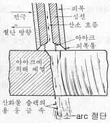
Fig.8
|