|
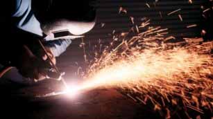
(1) Oxygen-fuel Gas Flame Gouging
Oxygen-fuel (oxyfuel) flame gouging offers fabricators a quick and efficient method of removing metal.
It can be at least four times quicker than cold chipping operations. The process is particularly
attractive because of its low noise, ease of handling, and ability to be used in all positions.
-
Process description
Flame gouging is a variant of conventional oxyfuel gas welding. Oxygen and a fuel gas are used to produce
a high temperature flame for melting the steel.
When gouging, the steel is locally heated
to a temperature above the 'ignition' temperature (typically 900deg.C) and a jet of oxygen
is used to melt the metal - a chemical reaction between pure oxygen and hot metal. This jet is
also used to blow away molten metal and slag. It should be noted that compared with oxyfuel cutting,
slag is not blown through the material, but remains on the top surface of the workpiece.
The gouging nozzle is designed to supply a relatively large volume of oxygen through the gouging jet.
This can be as much as 300 litre/min through a 6mm orifice nozzle. In oxyacetylene gouging,
equal quantities of oxygen and acetylene are used to set a neutral preheating flame.
The oxygen jet flow rate determines the depth and width of the gouge.
When the preheating flame and oxygen jet are correctly set, the gouge has a uniform profile and
its surfaces are smooth with a dull blue colour.
Operating techniques
The depth of the gouge is determined principally by the speed and angle of the torch.
To cut a deep groove the angle of the torch is stepped up (this increases the impingement angle
of the oxygen jet) and gouging speed is reduced. To produce a shallow groove, the torch is
less steeply angled, see above, and speed is increased. Wide grooves can be produced by
weaving the torch. The contour of the groove is dependent upon the size of the nozzle and
the operating parameters. If the cutting oxygen pressure is too low, gouging progresses
with a washing action, leaving smooth ripples in the bottom of the groove. If the cutting
oxygen pressure is too high, the cut advances ahead of the molten pool - this will disrupt
the gouging operation especially when making shallow grooves.
There are four basic flame gouging techniques which are used in the following types of application.
Progressive gouging
This technique is used to produce uniform grooves. Gouging is conducted in either a continuous
or progressive manner. Applications include removal of an unfused root area on the reverse side
of a welded joint, part-shaping a steel forging, complete removal of a weld deposit and preparing
plate edges for welding.
Spot gouging
Spot gouging produces a deep narrow U-shaped groove over a relatively short length. The process is
ideally suited to removal of localised areas such as isolated weld imperfections. Experienced
operators are able to observe any imperfections during gouging. These appear as dark or light
spots/streaks within the molten pool (reaction zone).
Back-step gouging
Once the material has reached ignition temperature, the oxygen stream is introduced and the torch moved
in a backward movement for a distance of 15-20mm. The oxygen is shut off and the torch moved
forward a distance of 25-30mm before restarting the gouging operation. This technique is
favoured for removal of local imperfections which may be deeply embedded in the base plate.
Deep gouging
It is sometimes necessary to produce a long deep gouge. Such operations are completed using the deep
gouging technique, which is basically a combination of progressive and spot gouging.
(2) Manual Metal Arc Gouging
The main advantage of manual metal arc (MMA) gouging is that it allows the operator to switch easily
from welding to gouging, or cutting, simply by changing the type of electrode.
-
Process description
As in conventional MMA welding, the arc is formed between the tip of the electrode and the workpiece.
MMA gouging differs because it requires special purpose electrodes with thick flux coatings
to generate a strong arc force and gas stream.
Unlike MMA welding where a stable weld pool
must be maintained, this process forces the molten metal away from the arc zone to leave a clean cut surface.
The gouging process is characterised by the large amount of gas which is generated to eject the molten metal.
However, because the arc/gas stream is not as powerful as a gas or a separate air jet, the surface of
the gouge is not really as smooth as an oxyfuel gouge or air carbon arc gouge.
Electrode
According to the size of gouge specified, there is a wide range of electrode diameters available to choose from.
These grooving electrodes are also not just restricted to steels, and the same electrode composition may
be used for gouging stainless steel and non-ferrous alloys.
Power source
MMA gouging can be carried out using conventional DC and AC power sources. In DC gouging, electrode polarity
is normally negative but electrode manufacturers may well recommend electrode polarity for their brand of
electrodes and for gouging specific materials. When using an AC power source, a minimum of 7OV open circuit
(OCV) is required to stabilise the arc.
Although most MMA welding power sources can be used for gouging, the current rating and OCV must
be capable of accommodating current surges and longer arc lengths.
Operational characteristics
The arc is struck with an electrode which is held at a normal angle to the workpiece (15 degrees backwards
from the vertical plane in line with proposed direction of gouging). Once the arc is established,
the electrode is immediately inclined in one smooth and continuous movement to an angle of around 15-20
degrees to the plate surface. With the arc pointing in the direction of travel, the electrode is pushed
forward slightly to melt the metal. It should then be pulled back to allow the gas jet to displace
the molten metal and slag. This forward and backward motion is repeated as the electrode is guided
along the line to complete the gouge.
To produce a consistent depth and width of gouge, a uniform rate of travel must be maintained,
together with the angle of electrode: 10-20 degrees. If the electrode angle becomes too steep,
in excess of about 20 degrees, the amount of slag and molten metal will increase. This is a result
of the arc penetrating too deeply. Digging the electrode into the metal causes problems
in controlling the gouging operation and will produce a rough surface profile. For gouging
in positions other than vertical, the electrode is always pushed forward. With vertical surfaces,
the electrode is directed and pushed vertically downwards.
Application
MMA gouging is used for localised gouging operations, removal of defects for example,
and where it is more convenient to switch from a welding electrode to a gouging electrode
rather than use specialised equipment. Compared with alternative gouging processes,
metal removal rates are low and the quality of the gouged surface is inferior.
When correctly applied, MMA gouging can produce relatively clean gouged surfaces.
For general applications welding can be carried out without the need to dress by grinding.
However when gouging stainless steel, a thin layer of higher carbon content material will
be produced - this should be removed by grinding.
(3) Air Carbon Arc Gouging
The main difference between this gouging technique and the others is that a separate air jet
is used to eject molten metal to form the groove.
-
Process description
Air carbon arc gouging works as follows.
An electric arc is generated between the tip of a carbon electrode
and the workpiece.
The metal becomes molten and a high velocity air jet streams down the electrode to blow
it away, thus leaving a clean groove. The process is simple to apply (using the same equipment as MMA welding),
has a high metal removal rate, and gouge profile can be closely controlled. Disadvantages are that
the air jet causes the molten metal to be ejected over quite a large distance and, because of high currents
(up to 2000A) and high air pressures (80 to 100 psi), it can be very noisy.
Application
As air carbon arc gouging does not rely on oxidation it can be applied to a wide range of metals.
DC (electrode positive) is normally preferred for steel and stainless steel but AC is more effective
for cast iron, copper and nickel alloys. Typical applications include back gouging, removal of surface
and internal defects, removal of excess weld metal and preparation of bevel edges for welding.
Electrode
The electrode is a non-consumable graphite (carbon) rod which has a copper coating to reduce electrode erosion.
Electrode diameter is selected according to required depth and width of gouge. Cutting can be precisely
controlled and molten metal/dross is kept to a minimum.
Power source
A DC power supply with electrode positive polarity is most suitable. AC power sources which are also constant
current can be used but with special AC type electrodes. The power source must have a constant current
output characteristic. If it does not, inadvertant touching of the electrode to the workpiece will cause
a high current surge sufficient to 'explode' the electrode tip. This will disrupt the operation
and cause carbon pick-up. As arc voltage can be quite high (up to 50V), open circuit voltage of
the power source should be over 60V.
Air supply
The gouging torch is normally operated with either a compressed air line or seperate bottled gas supply.
Air supply pressure will be up to 100psi from the air line but restricted to about 35psi from a bottled supply.
Providing there is sufficient air flow to remove molten metal, there are no advantages in using higher pressure
and flow rates.
Carbon pickup
Although carbon is picked up by the molten metal, the air stream will remove carbon-rich metal
from the groove to leave only minimal contamination of the sidewalls. Poor gouging technique
or insufficient air flow will result in carbon pick-up with the risk of metallurgical problems,
e.g high hardness and even cracking.
Operation
Gouging is commenced by striking the electrode tip on to the workpiece surface to initiate the arc.
Unlike manual metal arc (MMA) welding the electrode tip is not withdrawn to establish arc length.
Molten metal directly under the electrode tip (arc) is immediately blown away by the air stream.
For effective metal removal, it is important that the air stream is directed at the arc from behind
the electrode and sweeps under the tip of the electrode. The width of groove is determined by
the diameter of electrode, but depth is dictated by the angle of electrode to the workpiece
and rate of travel. Relatively high travel speeds are possible when a low electrode angle is used.
This produces a shallow groove: a steep angle results in a deep groove and requires slower travel speed.
Note, a steeply angled electrode may give rise to carbon contamination.
Oscillating the electrode in a circular or restricted weave motion during gouging can greatly
increase gouging width. This is useful for removal of a weld or plate imperfection that is wider
than the electrode itself. It is important, however, that weave width should not exceed four times
the diameter of the electrode.The groove surface should be relatively free of oxidised metal and
can be considered ready for welding without further preparation. Dressing by grinding the side-walls
of the gouge should be carried out if a carbon rich layer has been formed. Also, dressing by grinding
or another approved method will be necessary if working on crack-sensitive material such as high strength,
low alloy steel.
(4) Plasma Arc Gouging
The use of the plasma arc as a gouging tool dates back to the 1960s when the process was developed for welding.
Compared with the alternative oxyfuel and MMA gouging techniques, plasma arc has a needle-like jet
which can produce a very precise groove, suitable for application on almost all ferrous and non- ferrous materials.
-
Process description
Plasma arc gouging is a variant of the plasma arc process. The arc is formed between a refractory
(usually tungsten) electrode and the workpiece. Intense plasma is achieved by constricting the arc
using a fine bore copper nozzle. By locating the electrode behind the nozzle, the plasma-forming
gas can be separated from the general gas supply used to cool the torch/assist the plasma gas to
blow away molten metal (dross) from the groove.
The temperature and force of the constricted plasma arc is determined by the current level and
plasma gas flow rate. Thus, the plasma can be varied to produce a hot gas stream or a high power,
deeply penetrating jet. This ability to control quite precisely the size and shape of a groove
is very useful for removing unwanted defects from a workpiece surface.
Whilst gouging, normal precautions should be taken to protect the operator and other workers
in the immediate area from the effects of intense are light and hot metal spray. Unlike the oxyfuel
and MMA processes, the plasma arc's high velocity jet will propel fume and hot metal dross some
considerable distance from the operator. When using a deeply penetrating arc, noise protection is
an essential requirement.
Equipment
The power source for sustaining this gouging arc must have a high open circuit voltage,
usually well in excess of 100V. The torch is connected to the negative polarity of the power source
and the workpiece must be connected to the positive. The plasma torch is the same as the one used
for cutting; it will be either gas or water cooled and have the facility for single and dual gas operation.
Electrodes are normally tungsten for argon and argon-based gases. However, when using air
as the plasma gas, special purpose, for example hafnium tipped copper, electrodes must be
used to withstand the more aggressive, oxidising arc.
Plasma and cooling gases
Plasma gas can be argon, helium, argon - H2, nitrogen or air. Argon - 35%H2 is normally recommended
as a general- purpose plasma gas for cutting most materials. Alternative plasma gases are argon and helium.
Argon, a colder gas, will reduce metal removal rates. Helium, which generates a hot but less intense arc
than argon - H2, can produce a wider and shallower groove. Nitrogen and air are also used as plasma gases,
especially for gouging C-Mn steels. Although gas costs will be substantially reduced,
the groove surface profile will be inferior to that which can be achieved with argon - H2 gas.
Air is not recommended for gouging aluminium as this requires an inert or reducing gas. Argon,
nitrogen or air are all used as cooling gases. Use of argon will normally produce the best quality of gouge,
but nitrogen or air will reduce operating costs.
Operating techniques
Gouging is effected by moving the torch forward at a steady controlled rate. It is carried out in
a progressive manner to remove metal over a distance of 200 to 250mm. The jet can then be repositioned,
either to deepen or widen the groove, or to continue gouging for a further 200 to 250mm.
Principal process parameters are current level, gas flow rate, and speed of gouging. These settings
determine groove size and metal removal rate. In a typical gouging operation on C-Mn steel,
metal is removed at about 100 kg/hr at a speed of 0.5 m/min, and groove size will be
around 12mm wide and 5mm deep.
The torch stand-off and its angle to the surface of the workpiece have a major influence on speed of travel,
groove profile and quality of surface. The torch is normally held at a distance of 20mm from the workpiece
and inclined backwards to the direction of gouging at an angle of 40 to 45 degrees. Gouging will
remove up to approximately 6mm depth of metal in a single pass.
The torch stand-off should not be reduced to less than 12mm, to avoid spatter build-up on the nozzle
from the molten particles ejected from the groove. At standoff distances greater than 25mm, arc/gas
forces are reduced and this lessens the depth of penetration of the jet. By reducing the torch angle
to the workpiece surface, the plasma jet can be encouraged to 'skate' along the surface of the workpiece;
this produces a shallower and wider groove. By increasing the angle of the torch the plasma jet is directed
into the workpiece surface, resulting in a deeper and narrower groove.
|