(´ŮŔ˝ Ľł¸íżˇĽ´Â
flash welding = flash ¸Â´ë±â ŔúÇ׿ëÁ˘, butt welding = upset ¸Â´ë±â ŔúÇ׿ëÁ˘)
Both flash and butt welding processes can be performed using alternating current (AC) or direct current (DC) secondary currents with primary input power of single phase or three phase.
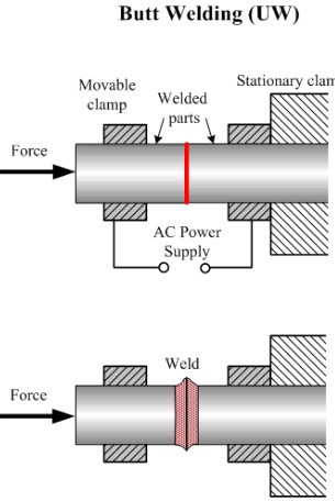
One of the earliest forms of resistance welding to be used in the metalworking industry is the butt welding process. Although flash welding and butt welding are accomplished on welding machines that are similar, the most notable exceptions are the applications of pressure and current.
In a basic butt weld, the two workpieces to be welded are first brought together under pressure. Current is then applied, heating the contact area enough to allow the applied pressure to forge the parts together. In other words, a butt weld is a single-stage operation of both current and pressure.
The pressure and current are applied throughout the weld cycle until the joint becomes plastic. The constant pressure (normally from an air cylinder) overcomes the softened area, producing the forging effect and subsequent welded joint. This is done without a change in current or pressure throughout the cycle.
The true butt weld has no flash splatter. The final upset at the weld joint is usually smooth and symmetrical. Very little ragged expulsion of metal is evident.
Examples of modern-day applications of the AC butt welding process are joining small-diameter wires and rods, such as coils for continuous line operations, band saw blade manufacture, and wire frame applications.
Developments in Butt Welding
Although butt welding was widely used during the early industrial years, it was limited because of the high current required to bring the ends of a large workpiece to the forging temperature. Careful end preparation was also needed. The welding surfaces of the workpiece had to be very clean, smooth, and parallel. If the proper preparation was not performed, hot spots in the weld face would be created from an uneven current flow.
Butt welding was thought to produce weaker welds than flash welding. The advance of modern microprocessor controls and the use of DC and finite control over the abutting surfaces has helped dispel this belief.
Early on, butt welding was limited to smaller machines of 5 to 100 KVA and single-phase AC. Larger applications required high currents. This high secondary current demand put a strain on the user's primary power supply and required large distribution equipment.
In later years, a three-phase DC power supply was applied to butt welding. A welding machine equipped with a three-phase DC power supply provides balanced line demand, reduced primary current, and a more even heating of the weld area. Inductive losses are minimized, allowing a greater freedom in machine design. Larger cross sections of both ferrous and nonferrous material have been successfully welded with the three-phase DC butt weld.
However, the three-phase DC power supply, with its rectification, physical size, and associated items required to support the butt weld system, involves increased costs. A three-phase control is required, as is increased water supply on the rectified secondary of the transformer.
Research studies have found that a narrower heat-affected zone (HAZ) can be produced on a three-phase DC butt welder. Additional tests have pointed out that there is no significant difference in weld quality of three-phase DC butt weld over single-phase AC flash welding.
How Flash Welding Works
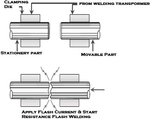
The term "flash welding" is fairly self-descriptive?a "flashing" action is produced during the process. The heat is produced in the flash welding process by the flashing action resistance at the interface surfaces rather than contact resistance, as in the butt weld process. Whereas butt welding is a single-stage operation, flash welding is a two-stage process.
The first stage is the flashing action. The current applied to the workpieces produces a flashing or arcing across the interface of the two butting ends of the material. The flashing action increases to the point of bringing the material to a plastic state. This flashing action forms a HAZ very similar to a butt weld.
Once the area has become plastic and reached the proper temperature, the second stage of the operation begins ? the upset or forging action. The two ends of the workpieces are then brought together with a very high force sufficient enough to cause the material to upset. This forces the plastic metal along with most of the impurities out of the joint.
Smooth, clean workpiece surfaces are not as critical with this process as they are for butt welding, because the flashing action burns away irregularities at the weld surfaces (see Figure 1). This allows joining of a wide variety of materials. Such items as wide, thin sheets of material; tubing; forgings; and ferrous and nonferrous materials can successfully be welded.
With the single-phase AC power supplies (transformers), applications with large cross-sectional areas can be welded with lower current demands because of the flashing action.
Flash welding can also be applied as shown in Figure 2. This door mitre example has rough edges, and the two ends do not perfectly match. Subsequent sanding and removal of excess flash and upset material with a final polish eliminates any sign of a joint. The flash action eliminates any preparation of the sheared edge of the extruded sheet metal workpiece.
In other applications, the flash or slag can be knocked loose for removal. The upset underneath the slag is solid metal similar to a butt weld and requires a cutting operation, trimming, or deburring for removal.
The disadvantage of this process is the flash itself. The operator and the surrounding area need to be protected, and smoke and fumes must be removed. The resultant slag particles build up around the machine surfaces, and frequent cleaning is needed.
Controlling the Flash Welding Process
The key to the flash welding process is the control of the two workpieces toward each other during the flashing operation.
Some of the earliest mechanisms for controlling the distance between the two workpieces for the proper flashing action were hand-operated. The operator controlled the current by a thumb button or automatic trip.
The operator became very skilled in controlling the amount of pressure of the two workpieces and resulting flashing action. By observing the heat color of the area and the expulsion of the material, the operator knew when to apply heavier pressure for the second stage (or upset portion) of the flash weld.
Later developments included a motor-driven, variable-speed drive system tied to a gear-reducing unit and cam. This combination provided variable speed, bringing the two workpieces together with acceleration toward the end of the flash welding stage. This acceleration is required because of the increased amount of material expelled as the temperature increases, which in turn increases the resistance between the two materials.
An upset block provided on the cam allowed for the second stage (upset) to be initiated at the proper time. The current was initiated and subsequently turned off by limit switches strategically placed to work in conjunction with the cam, and it could be turned on or off to facilitate the proper heating.
As alloys and special materials were being developed in the industry, they required an entirely different rate of rise on the cam and a change of upset. This caused the cam to be altered or changed when going from one cross section to another or from one alloy to another.For instance, aluminum alloys require a rapid or high-speed upset because of their narrower HAZ. This caused an extremely rapid rise on a cam to accommodate these alloys, and success was mediocre at best.
Air over oil cylinders were then used but were limited to smaller cross sections of workpieces.
Another way to control the movement of the two workpieces in flash welding is with a hydraulic/servo valve combination. This provides control and high pressures with rapid acceleration. Flash welding machines with hydraulic operation in use today can generate upset pressures of more than 200 tons.
Most flash welding machines use single-phase AC power supplies. As with the butt weld process, three-phase DC can also be used. Although this does not eliminate the flashing action, it does result in reduced primary current, less material loss, and a narrower HAZ. However, capital costs are higher, and requirements for the process are the same as for DC butt welding, mentioned previously.
Developments in Flash Welding
Controls. Flash welding's versatility has increased with the addition of electronic and microprocessor controls that accurately control and monitor the flash welding process. These controls include:
1. Feedback information to determine velocity and acceleration of the two workpieces as they come together.
2. Current monitoring.
3. Flash voltage action.
Preflash and Preheating. Other developments include additional stages before the flash welding (see Figure 3). These include a burn-off or preflash that allows the ragged ends of unprepared parts to be squared up before a second stage of preheating. The preheating portion of the flash welding operation allows for heat to be generated into the interface of the weld without a discernable amount of material being lost.
This preheating action is an oscillation of the two workpieces against each other. After the two ends of the workpieces are brought together, the resistance in the material allows heat to be generated, and the two ends are pulled apart (before becoming molten), allowing a cooling effect at the interface of the material.
Once the ends begin to cool and solidify, the process is repeated and continued in a rapid motion until heat is generated back into both workpieces. With this process:
1. A large cross-sectional area can be welded with lower current demand.
2. Heat can be generated in high-strength alloys without a large loss of material by the flashing action.
3. The temperature gradient remains more uniform.
Once the proper HAZ has been reached with the preheat stage, the flash weld stage is then initiated for a short period of time, followed by the upset or forging force.
In many cases, when welding steels with extremely high alloys or carbon content, cracking is possible if the weld is cooled too rapidly to room temperature. If the preheating is insufficient, the cracking may be prevented by a final process in the flash weld called postheating. The postheat cycle can be incorporated in a flash weld machine and adjusted for the desired temperature.
|